
A feature of this scratch build is that I’m trying a couple of things that are new to me. One is a coreless motor and this has been sourced from a company in the UK. When the motor and gearbox arrive in the post I’ll write more about it. Another element that is new to me is the use of tiny ball race bearings that sit inside CNC machined horn guides. If the words horn guides, horn blocks and sprung bearings are all a bit of a mystery to you, never fear: all this refers to is a small track that is fixed to the inside of the locomotive frames that allow the bearing that holds the axles in place a small degree of movement up and down. This is often accompanied by a small spring that is intended to provide some degree of suspension, although the action is somewhat reversed in a model loco compared to a car or a real locomotive in that the system is designed to keep the wheel in contact with the surface of the rail rather than provide a smoother ride to passengers. Small white metal people rarely complain about the ride 🙂
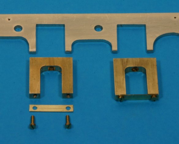
The Hobby Holidays horn-guides are the large chunks of brass in the centre of the photo. My hand cut frames are at the top and the short length of brass strip with holes in it and the small 12 BA screws can be seen at the bottom of the photo.
I’d first heard about using small ball races for the bearings of model locos from a friend in the UK by the name of John Birch. He’d installed these into a model of NSWGR 50 class locomotive he was building from an O-Aust kit. He hasn’t finished this loco yet but his early reports about the ball race bearings had been very positive so I purchased a set of these for my own use when I finally got to the point where I was building another loco. I’ve recently done some thinking about whether I wanted to use these in my 20 class project and today I came to a final decision that I would in fact use them. The horn-guides, ball race bearings and some other parts come as a small kit from Hobby Holidays in the UK. This small hobby and holiday business make and sell lots of useful kit, their website is well worth a visit. There are two types of horn guides available from HH, plain and detailed. As these items will be on the inside of the loco frames and barely visible I decided to go with the plain, CNC milled variety. These are what you can see in the photo.
This week I essentially completed the cutting and filing of the new frames, so today I decided to make a start on preparing the horn guides for use in the loco chassis. The guides are basically 6 horseshoe-shaped blocks of accurately CNC milled brass. They will be positioned and soldered into the chassis later. These guides allow a degree of movement to the wheels which improves adhesion and power pickup. Any properly installed system of springing or compensation via the use of moveable horn-blocks will provide this. The ball races are just an addition to the normal arrangement of using machined brass bearings. The guides I’m using have one hole let into the top to allow the positioning of a brass bolt to allow for the height of the wheels to be adjusted, however there is no provision for some way to retain the bearings in the guides from below. When I contacted John and asked him what he had done to stop the axles and bearings dropping out of the guides, he said he’d soldered a strip of brass across the opening after installation of the wheels.
Huh? I’ve got precision milled hornguides and tiny, high-tech ball races acting as bearings and I’m going to hold all this together with a strip of soldered brass. Not likely! 🙂 I like to be able to get at things for maintenance and repair and while soldering a strip of brass across the opening would certainly work at holding the bearings in place, it would make removal at a later date not impossible, but difficult. So today I drilled some small holes into the base of each leg of the horn-guides and tapped these 12BA to allow the insertion of small cheese head bolts. I then cut and drilled some holes into some lengths of 16mmX3mmX.25mm brass strip to be held in place by the bolts. These will hold the axles in place but will allow me to remove them if needed without the use of a soldering iron. You can see the result in the above photo.
